Table of Contents
4145A Semiconductor Parameter Analyzer
| First Catalog | 1983 |
|---|
Designed for production line and laboratory use, the HP 4145A was the electronics industry's first stand-alone instrument capable of complete DC characterization of semiconductor devices and materials. It stimulates voltage and current-sensitive devices, measures the resulting current and voltage responses, and displays the results in a user-selectable format (graph, list, matrix, or schmoo) on a built-in CRT display.
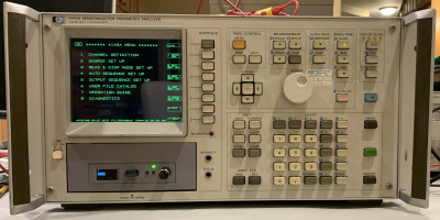
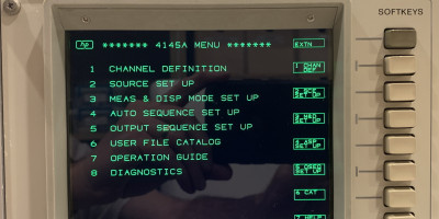
The photos show an analyzer that has been upgraded with a modern LCD display (NewScope-5 from SIMMCONN Labs) and a “Gotek” floppy emulator to replace its original, proprietary 5.25“ Floppy Drive.
HP 16058A Test Fixture Operating Manual
Service Note 14 - Flexible Disk Drive
Comparison to Tektronix Curve Tracer (576, 577)
Installation of "Gotek" Floppy Drive Emulator (running "FlashFloppy")
There are several articles/videos on the Internet on retrofitting a “Lotharek” HxC floppy emulator to the analyzer.
Below, the steps to use one of the newer “Goteks” (with the latest 435-based MCU and an OLED display) are outlined. They usually come with “FlashFloppy” already installed.
- Remove the existing 5.25 drive.
- Retrofit a 34-pin IDC connector to the 4145A Floppy cable.
- Use a power adapter to connect the Gotek to the 4-pin Molex of the 4145A.
- Connect Pin 6 and Pin 34 on the floppy drive with a jumper wire.
- Format a USB stick for the FAT32 filesystem.
- Load the configuration and binary files for the boot disk onto the USB stick.
- To install the Gotek into the 5.25 bay of the 4145A, either use parts from one of the universal floppy drive adapter kits that can be found on eBay. Or create a custom adapter if you are mechanically skilled.
- Put everything together, turn the instrument on, and it should boot from the Gotek.
Zip-file with the two configuration files and the binary file for the boot disk: Gotek FlashFloppy Files
Credits:
- Many ideas were taken from this excellent video: HP 4145A Semiconductor Parameter Analyzer Disk Drive Replacement
- The boot disk binary file (“DSKA0000.HFE”) can also be obtained from here: https://github.com/exclusivelyhp/4145A.
- Article on putting together the “IMG.CFG” file: http://w6akp.com/projects:hp_4145a_virtual_floppy
- FlashFloppy site: https://github.com/keirf/flashfloppy
- Jared Cabot's video and helpful information with regards to the 1345A display: https://youtu.be/53asomSXkXQ?si=rld6QaL18WURdmna
Installation of HxC2001 Floppy Drive Emulator (Jared Cabot's Notes)
The HP 4145A can be adapted to accept the HxC2001 Floppy Drive Emulator.
1. Unzip the disk image files and copy them to the root of the Floppy emulator.
2. Install a 34 pin Female IDC 2.54mm pitch socket connector to the Floppy drive ribbon cable connected to the HP4145A. This cable cannot be removed without significant work. Adding the connector will save you a lot of heart-ache. A simple press fit connector will do just fine. Be sure pin 1 is located on the same side as the original floppy drive connector. You do not need to remove the old floppy drive connector either. The added benefit is the upgrade can always be removed and the old drive put back in, not that you would want to though.
3. A bit of hardware modifications, you will need to add two resistors and a jumper wire to the HxC board. a. Add a 1K 0603 to R9, This is a pull up resistor. b. Add a 1K 0603 to R4, This is a pull up resistor. c. Add a jumper wire from pin 34 to pin 6, Pin 6 is not connected to anything on the emulator however pin 6 is used by the HP4145A to indicate that a disk is inserted. Without this jumper you will get an “Error M02” on the display.
4. Set the dip switches, they should be 10010000 (left to right when the floppy connector is facing up and away from you).
5. Insert the SD card and power up the unit. It should now be working.
HP 4145A - Power Transistor Measurement Setup
HP 4145A - Power Transistor Measurement Setup
Also published on groups.io: https://groups.io/g/HP-Agilent-Keysight-equipment/message/140475
HP 4145A - Miscellaneous Repair Notes
- Front panel push-buttons - if they are “clicky” (which is a well-known problem) - Take the front panel off, remove the PCB with all the switches, and use the Isopropyl alcohol method for cleaning. One sample thread is here: https://groups.io/g/HP-Agilent-Keysight-equipment/message/138483
- Rotary Pulse generator - if not working, try the information from this groups.io topic “https://groups.io/g/HP-Agilent-Keysight-equipment/message/6724” to fix it.
- Instrument fan: The HP part number is 3160-0391. A suitable replacement is this: https://a.co/d/7s5Tr1T. More info on the topic: https://groups.io/g/HP-Agilent-Keysight-equipment/message/139316
- YouTube video describing how to fix the intensity control: https://youtu.be/DxCr5CrAIr8?si=wro-JmeiFyCLlV3T
- Test leads/cables - see post “https://groups.io/g/HP-Agilent-Keysight-equipment/message/115414”.
HP 4145A - Boot Floppy Duplication
There is an interesting approach to read and write the 5.25” boot disk for the 4145A. Unlike the 4145B, the 4145A does not have the built-in capability to create boot floppy copies.
YouTube video: https://youtu.be/ZCxzYmUX3WA?si=dTzME4VWEdHpyV8N
Web site with the details: https://www.kitsune-denshi.net/equipment:hp4145a
HP 4145A - Boot Floppy Duplication Using "Greaseweazle"
Sample Setup:
- Lenovo W520 Laptop running Manjaro LINUX
- Greaseweazle V4.1 HW
- Greaseweazle 1.23 SW (downloaded from GitHub; installed per the instructions)
- 5-1/4“ Floppy Drive, Toshiba FDD6471L0K Rev A (Drive was jumpered and connected to the Greaseweazle as “Drive B”)
- Maxell MD2-D Floppy Disks
- One original 4145A Boot Disk, HP P/N 04145-8500 Rev A5
Steps:
- Reset GW:
> gw reset - Insert Source Disk into the Drive
- Read the contents of the source floppy and save it to “4145A_Boot.imd”:
> gw read –drive b –tracks 'c=0-39:h=0' –format=ibm.scan 4145A_Boot.imd - Insert Destination Disk into the Drive
- “Erase” the destination disk:
> gw erase –drive B –tracks 'c=0-39:h=0' - Write “4145A_Boot.imd” back to the destination floppy:
> gw write –drive b –tracks='c=0-39:h=0' 4145A_Boot.imd
This should do it! I inserted the copied disk into my 4145A and it booted fine. I did another round of copying, using the newly created disk as the source, and the second generation copy also booted without issues.
HP 16058A Custom Adapter Plates
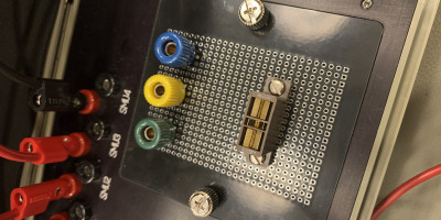
Board #1 with a bunch of standard through-holes, customizable to all kinds of things. Gerber Files.

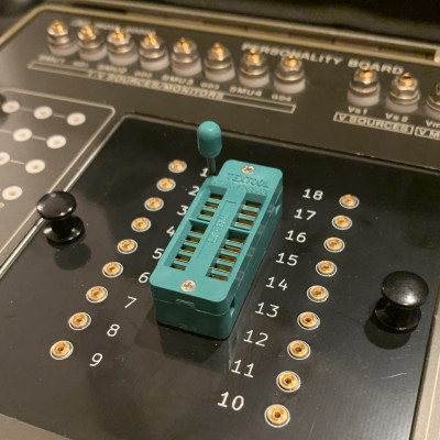
Board #2 holds a standard 18-pin socket and connects to 1mm jacks, modeled after the “HP 16058-60007 Test Fixture Dual-In-Line 18 Pin”. Gerber Files.
Material used:
- 18-pin DIP Socket - 3M Textool ZIF or equivalent
- 1mm PCB-mounted test jacks: 18x Harwin H3185-05 (Mouser part 855-H3185-05)
- Snap-in grommets and plunger (HP numbers 1390-0366 and 1390-0365) to hold the adapter boards in place - the HP parts are nowhere to be found. However, the Leviton 47615-NYP push-lock pins fit perfectly and are widely available: https://a.co/d/9L8iwma
HP 4085M - Switching Matrix
The HP 4145A/B could be paired with the HP 4085A Switching Matrix as part of the HP 4062UX/UF semiconductor test system. This setup enabled the 4145A/B’s channels to be flexibly connected to up to 48 pins of a separate test fixture.
This system has been, and continues to be, used for semiconductor engineering verification and wafer-probing-based characterization.
To set up the system, the following components are required:
- HP 4084A/B Switching Matrix Controller
- Connection cable (04085-61671)
- Adapter plate (16078A)
- Shorting connector (04145-61623)
- 36-pin Centronics cable (to interconnect switch matrix and controller)
- Triaxial and coaxial BNC cables
The system was typically controlled by custom software running on an HP 9836 or 9816 computer, but it can also be operated via HPIB commands.


